
Search


FPC Bending: Definition, Design & Manufacturing Optimization, Key Considerations | Huaruixin Electronics
- Jan 14,2026
-
Share
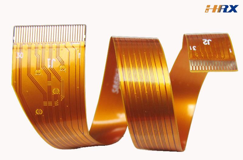
In the era of lightweight, miniaturized, and foldable electronic devices, Flexible Printed Circuits (FPC) have become indispensable core components, thanks to their excellent flexibility, space-saving advantages, and reliable electrical conductivity. Among the many performance indicators of FPC, bending performance is a crucial factor determining the service life and reliability of electronic products, especially in scenarios such as foldable smartphones, wearable devices, automotive electronics, and medical endoscopes. This article will systematically explain the definition of FPC bending, elaborate on the optimization strategies in design and manufacturing, analyze the key issues that need attention, and share the professional solutions of Shenzhen Huaruixin Electronics Co., Ltd. in handling FPC bending performance as a global ODM/OEM manufacturer of FPC, PCB, and rigid-flex boards.
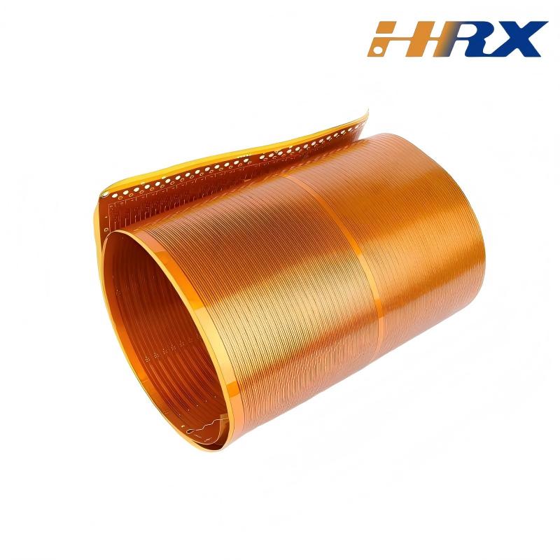
1. What Is FPC Bending? Definition & Classification
FPC bending refers to the process in which the flexible printed circuit undergoes elastic or plastic deformation under external force to adapt to the spatial layout requirements of electronic devices, while maintaining the integrity of its electrical performance and structural stability. According to industry standards such as IPC-2223 and JEDEC JESD22-B113 , FPC bending is usually classified based on application scenarios, bending frequency, and stress state, which helps to formulate targeted design and manufacturing schemes.
From the perspective of bending frequency, it can be divided into static bending and dynamic bending: Static bending refers to the FPC being in a fixed bent state for a long time, such as the FPC fixed in the narrow space of automotive electronic components, which requires maintaining structural stability for more than 1000 hours without delamination or line breakage . Dynamic bending refers to the repeated cyclic bending of FPC during the use of the product, such as the FPC in the hinge area of foldable mobile phones and the connection part of smart watch wristbands, which needs to withstand tens of thousands or even hundreds of thousands of cyclic bending without failure.
From the perspective of bending radius, it is divided into minimum bending radius (MBR) and working bending radius. The minimum bending radius is the smallest radius that FPC can withstand without permanent damage or performance degradation, which is closely related to the thickness of FPC, material properties, and layer structure. Generally, the minimum bending radius should be at least 10 times the thickness of FPC . The working bending radius is the actual bending radius used in the product, which is usually designed to be larger than the minimum bending radius to ensure sufficient reliability margin.
2. How to Improve FPC Bending Performance: Design & Manufacturing Strategies
Improving FPC bending performance requires systematic optimization from two core links: design and manufacturing. Only by integrating material selection, structural design, process control, and other aspects can we effectively enhance the bending durability and reliability of FPC. Shenzhen Huaruixin Electronics has formed a set of mature solutions based on years of ODM/OEM production experience in the global FPC field.
2.1 Design Optimization: Lay the Foundation for Bending Performance
Design is the premise of determining FPC bending performance. Reasonable design can avoid potential bending failures from the source. Huaruixin Electronics focuses on the following design points in FPC bending performance optimization:
Material Selection Optimization: The choice of base material, copper foil, and adhesive directly affects the bending performance of FPC. We prioritize high-performance polyimide (PI) base materials with excellent fatigue resistance and rebound resilience, which can reduce stress accumulation during repeated bending . For the conductive layer, rolled annealed (RA) copper foil with high ductility is selected, which can improve the dynamic bending life by about 30% compared with ordinary electrolytic copper foil . In terms of adhesive, low elastic modulus flexible adhesive is used to reduce the interlayer peeling force caused by bending and prevent delamination between the base material and copper foil .
Layer Structure Design: Symmetrical layer structure design is adopted to ensure that the layer structures on both sides of the bending surface centerline are as symmetrical as possible, which can effectively avoid neutral layer offset and reduce stress concentration. For high-bending-demand FPC, single-layer or double-layer structures are preferred to avoid excessive interlayer stress caused by multi-layer stacking . At the same time, the overall thickness of FPC is controlled as thin as possible to reduce the bending moment during bending and lower the risk of fracture.
Circuit Layout Optimization: In the bending area, the circuit is arranged parallel to the bending direction to reduce the tensile and compressive stress on the circuit during bending . Arc routing is adopted instead of right-angle turning to avoid stress concentration at the corner. The line width in the bending area is appropriately widened to balance the contradiction between wiring density and mechanical durability—narrow line width is conducive to improving wiring density but is prone to breakage, while wide line width enhances mechanical strength but may increase stress accumulation. In addition, dense circuits, solder joints, and vias are avoided in the bending area, because vias are prone to microcracks during bending, leading to conduction failure .
Bending Area Reinforcement Design: For the edge of the bending area that needs appropriate support, flexible PI reinforcement sheets (thickness 25-50μm) consistent with the base material are used instead of rigid reinforcement materials such as FR4 . The reinforcement range only covers the edge of the bending area (1-2mm away from the bending axis) to avoid affecting the flexibility of the core bending area. For non-bending areas such as connectors and solder joints, PI or FR4 rigid reinforcement sheets are added to provide support and avoid deformation during plugging and pressing .
2.2 Manufacturing Process Control: Ensure the Implementation of Design Indicators
Excellent design needs to be guaranteed by sophisticated manufacturing processes. Poor process control will make the excellent design "invalid". Huaruixin Electronics strictly controls the key processes related to FPC bending performance:
Lamination Process Optimization: The lamination of base material, adhesive, and copper foil is the foundation to ensure interlayer bonding force. We strictly control the lamination parameters: temperature 180-200℃ (to ensure that the adhesive is fully melted without aging the PI base material), pressure 1.5-2MPa (to ensure close bonding without bubbles), and time 30-60 seconds (adjusted according to the adhesive thickness) . Before lamination, the surface of the base material and copper foil is cleaned with isopropanol to remove oil stains, and the oxide layer on the copper foil surface is treated to ensure that the bonding force is not less than 0.8N/mm, avoiding copper foil peeling during bending.
Molding and Cutting Process: Laser cutting is used for the bending area instead of mold stamping to avoid burrs and plastic deformation caused by stamping . We use CO₂ laser with a wavelength of 10.6μm for cutting, which can ensure the smoothness of the cutting edge of the PI base material, and the edge roughness Ra ≤ 0.05μm after laser polishing. For non-bending areas that use mold stamping due to cost constraints, secondary grinding is performed to remove burrs, ensuring that the burr size is less than 0.05mm and avoiding stress concentration caused by burrs.
Surface Treatment Process: Prefer electroless silver plating or OSP surface treatment instead of thick gold plating (thickness >1μm). The electroless silver plating layer (thickness 0.8-1.2μm) has good flexibility and strong bonding force with copper foil, which will not reduce the bending life due to increased rigidity. After surface treatment, a 3M 610 tape adhesion test is carried out to ensure that the surface treatment layer does not fall off after repeated bending.
Environment and Quality Control: During the processing, the environmental humidity is controlled at 40%-60% to prevent moisture penetration, and ion fans are equipped to take anti-static measures to avoid electrostatic breakdown . For ultra-thin multi-layer boards, pre-baking treatment (150℃/8 hours) is carried out to release internal stress and ensure flatness. After production, each batch of FPC undergoes strict bending fatigue tests in accordance with IPC-TM-650 2.4.9.1 and other standards to ensure that the bending life meets the design requirements.
3. Key Issues to Note in FPC Bending Performance Control
In the process of optimizing FPC bending performance, there are many key issues that need to be paid attention to, which are also the focus of Huaruixin Electronics' quality control:
Neutral Layer Offset Problem: When FPC is bent, the outer side is under tensile stress and the inner side is under compressive stress, and there is a "neutral layer" with no strain in the middle . If the copper circuit deviates from the neutral layer, it will bear significant tensile stress, especially at the edge of the outer bend, which will easily become the starting point of crack initiation. Therefore, it is necessary to accurately calculate the position of the neutral layer through finite element simulation (FEA) and adjust the layer structure to make the copper circuit as close to the neutral layer as possible.
Environmental Adaptability Problem: The bending performance of FPC is greatly affected by the environment. High temperature (>60℃) will soften the PI base material and reduce its strength, while low temperature (<-20℃) will make the PI base material brittle, both of which will shorten the bending life <superscript>3. Huaruixin Electronics conducts high and low temperature cycle tests (-40℃~85℃) on FPC products to ensure that the bending performance is stable in different environmental conditions.
Unreasonable Reinforcement Problem: Rigid reinforcement sheets such as FR4 are absolutely not allowed in the bending area. Their elastic modulus is 10-20 times that of PI, which cannot deform with the base material during bending, leading to stress concentration at the edge of the reinforcement sheet and rapid fracture . The size of the reinforcement sheet in non-bending areas should be 1mm larger than the pad on each side to avoid open circuits caused by creases at the edge of the pad.
Test and Verification Problem: Bending performance cannot be judged only by theoretical design. It is necessary to carry out targeted bending tests according to the actual application scenarios . For example, FPC for foldable mobile phones needs to pass 100,000 times of 180° folding tests (radius 0.5mm), and FPC for wearable devices needs to pass 50,000 times of 90° reciprocating bending tests (radius 1mm) with a resistance change of ≤5%.
4. Huaruixin Electronics' FPC Bending Performance Solution
As a global ODM/OEM manufacturer specializing in FPC, PCB, and rigid-flex boards, Shenzhen Huaruixin Electronics Co., Ltd. has integrated the above design and manufacturing experience into the whole process of product research and development and production, forming a one-stop solution for FPC bending performance optimization:
First, we provide customized material selection solutions according to the customer's product application scenarios (static/dynamic bending, environmental temperature, bending frequency, etc.), and select the most suitable PI base material, copper foil, and adhesive through material performance tests and bending life verification.
Second, our professional R&D team uses advanced finite element simulation software to optimize the layer structure and circuit layout of FPC, accurately control the position of the neutral layer, and avoid stress concentration.
Third, we have established a strict process control system, using laser cutting, precision lamination, and other advanced processes to ensure the stability of product quality.
Finally, we provide comprehensive testing and verification services, including dynamic bending test, static bending test, high and low temperature cycle test, etc., to ensure that the FPC bending performance meets the customer's requirements.
If you have FPC, PCB, or rigid-flex board project requirements, Shenzhen Huaruixin Electronics Co., Ltd., as a professional manufacturer with rich experience in global ODM/OEM production, is ready to serve you at any time. For more industry knowledge, you can also visit our website: www.hrxfpc.com to learn more information or email sales@hrxfpc.com for consultation, so that we can communicate, learn and guide each other.

Let’s talk! We’ll provide the perfect solution for you!
-
 Huaruixin Electronics mainly produces printed circuit boards as the core business, to provide customers with one-stop solutions for FPC/PCB production, components sourcing and Assembly.
 - WHAT WE DO — PCB Design Solutions — Flex PCB Production — Components Sourcing — FPC&PCB Assembly
- PRODUCTS — Single Sided Flexible Circuits — Double Sided Flexible Circuits — Multilayer Flexible Cirucits — Rigid-Flex Circuits — FPC Assembly — PCB Assembly
- CAPABILITY — FPC Capability — Rigid-Flex Capability — PCB Capability — Assembly Capability
- Copyright © 2024 Shenzhen Huaruixin Electronics Co., Ltd. All Rights Reserved.
- Design By BONTOP