
Search


Why is FPC Gold Finger Reinforcement Thickness Always Inaccurate? Shenzhen Huaruixin's Expert Analysis and Solutions
- May 08,2025
-
Share
In the highly specialized domain of Flexible Printed Circuit (FPC) manufacturing, the accurate calculation of gold finger reinforcement thickness remains a persistent conundrum for engineers and industry professionals. Gold fingers, also known as edge connectors or contact pads, are critical components in FPC assemblies (FPCA), facilitating electrical interconnections between various electronic devices. These conductive pads, typically plated with gold through processes like electroplating or electroless nickel immersion gold (ENIG), derive their name from their characteristic finger - like arrangement and golden appearance. Despite their significance in ensuring reliable electrical performance, determining the precise thickness of the reinforcement material, often Polyimide (PI) film, around these pads continues to pose substantial challenges. As a leading global ODM/OEM manufacturer specializing in FPC, PCB, and Rigid - Flex Printed Board production, equipped with state - of - the - art manufacturing facilities and a team of seasoned experts, Shenzhen Huaruixin Electronics Co., Ltd. has conducted in - depth research to uncover the root causes and develop effective solutions.
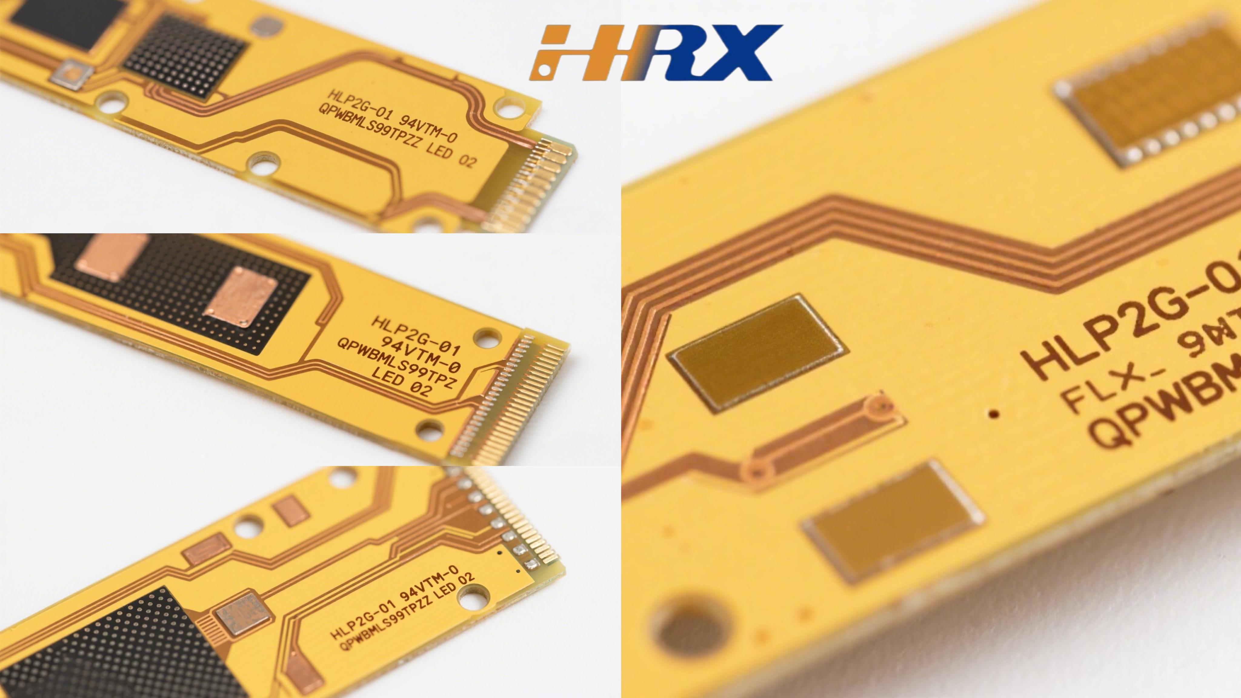
Our engineering team at Shenzhen Huaruixin Electronics Co., Ltd. emphasizes that multiple interrelated factors contribute to the inaccuracies in FPC gold finger reinforcement thickness calculations. One of the primary culprits lies in the complex relationship between the FPC's overall thickness, coverlay (solder mask) thickness, and copper foil thickness. In standard FPC manufacturing, the specified board thickness encompasses the cumulative thickness of all dielectric layers (including coverlay), copper foil layers on both the top and bottom surfaces, and any additional insulating or reinforcing materials.
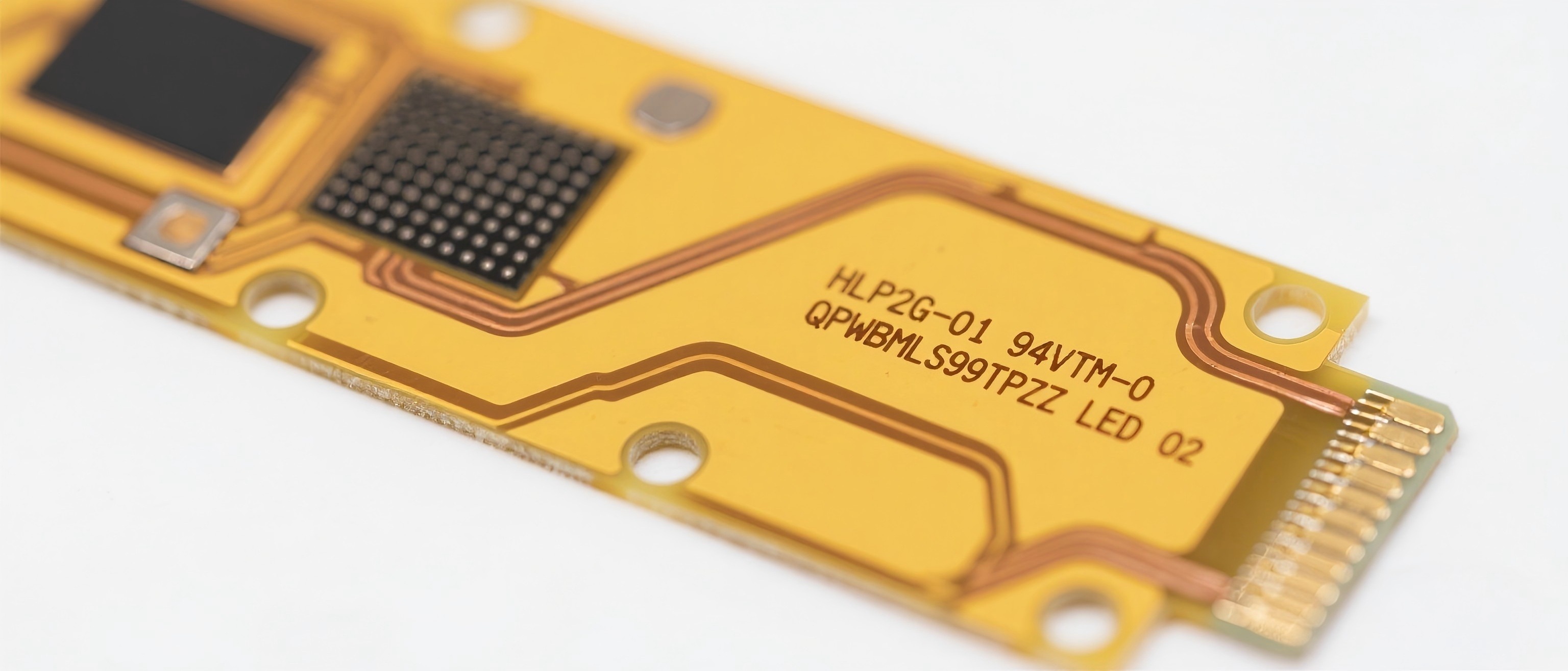
However, gold finger conductive pads are intentionally left uncovered by the coverlay to ensure optimal electrical conductivity and mechanical durability. This means that when calculating the total thickness at the gold finger area, the thickness of the absent coverlay layer must be subtracted from the overall board thickness. Failure to account for this precisely can lead to significant discrepancies in the calculated reinforcement thickness.
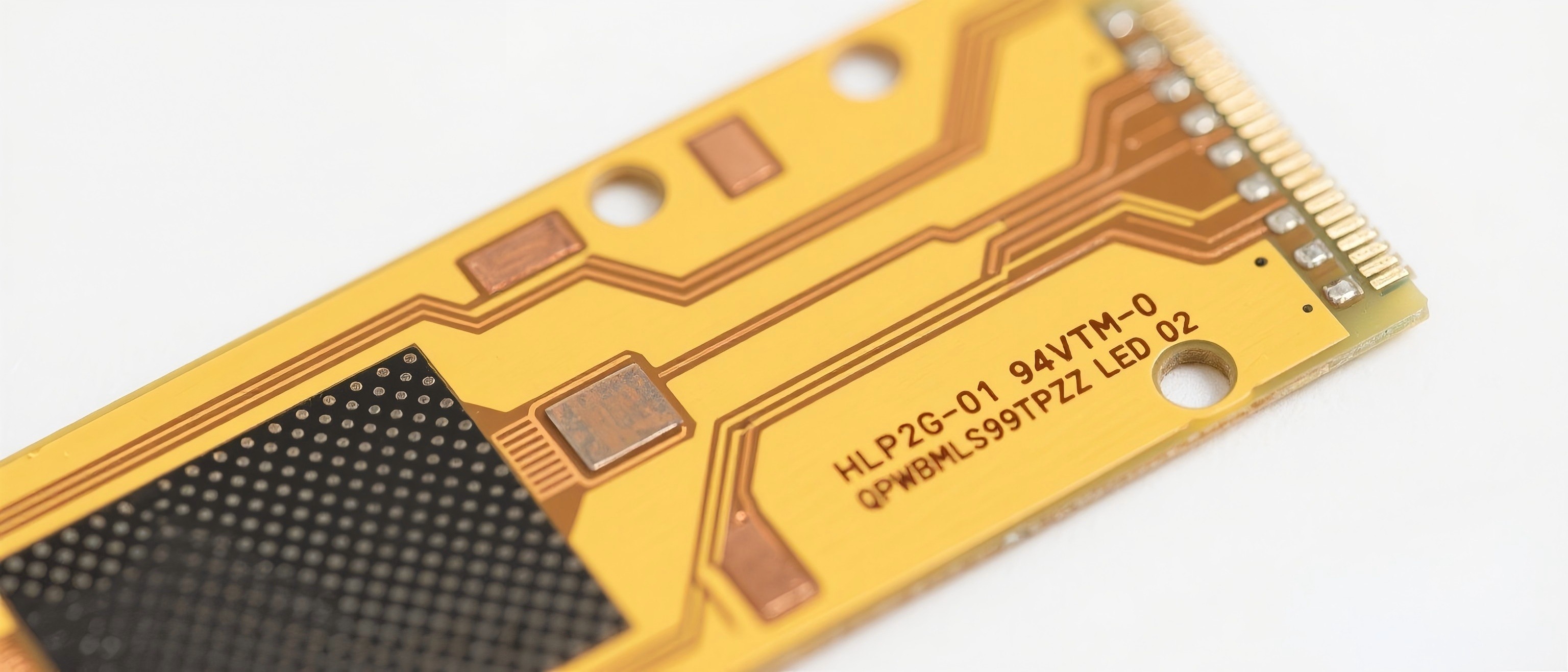
Moreover, the presence or absence of a copper layer on the backside of the gold finger further complicates the calculation process. In cases where there is no copper layer on the back of the gold finger, an additional adjustment for the missing copper foil thickness is required. This factor is often overlooked by many manufacturers, resulting in miscalculations of the reinforcement thickness needed to meet the desired overall FPC thickness specification. Additionally, other variables such as the type of adhesive used in the coverlay, the dielectric constant of the materials, and manufacturing tolerances also play crucial roles in influencing the final thickness, adding another layer of complexity to the calculation.
To address these multifaceted challenges, Shenzhen Huaruixin Electronics Co., Ltd. has developed a comprehensive and systematic approach. We begin by establishing clear and detailed relationships between board thickness, copper thickness, coverlay thickness, and other relevant parameters based on our extensive product development experience and in - house testing data. Our engineers have created detailed technical matrices and data tables that illustrate these relationships under various scenarios, providing a reliable reference for accurate calculations.
In terms of calculation methodologies, we have formulated two distinct sets of guidelines. For gold fingers with a copper layer on the backside, the calculation primarily involves subtracting the coverlay layer thickness from the target total thickness. This adjustment compensates for the lack of coverlay at the gold finger area, ensuring that the calculated reinforcement thickness aligns with the overall thickness requirements. When dealing with gold fingers without a backside copper layer, a two - step subtraction process is employed. First, the coverlay layer thickness is subtracted, followed by the copper foil thickness of the absent layer. This comprehensive approach enables us to accurately determine the appropriate thickness of the Polyimide (PI) reinforcement, taking into account all relevant factors and manufacturing tolerances.
To further enhance the accuracy and efficiency of the calculation process, we have developed an advanced, user - friendly online calculation tool. This innovative tool incorporates the latest industry standards and our proprietary calculation algorithms. Users can simply input the desired total thickness, select the relevant board thickness from a comprehensive dropdown menu, indicate whether there is a copper layer on the back of the gold finger, choose the coverlay type and color, and even input additional parameters such as adhesive thickness and dielectric constant if required. With just a few clicks, the tool generates the precise PI reinforcement thickness, significantly reducing the margin for human error and streamlining the FPC design and manufacturing process.
At Shenzhen Huaruixin Electronics Co., Ltd., we are committed to sharing our technical expertise and promoting innovation in the FPC manufacturing industry. Whether you are a seasoned engineer, a product designer, or a business looking for high - quality FPC solutions, we invite you to connect with us. Visit our website at www.hrxfpc.com to explore our comprehensive range of FPC, PCB, and Rigid - Flex Printed Board products, access detailed technical documentation, and stay updated on the latest industry trends. For personalized consultations, project inquiries, or to discuss custom FPC requirements, feel free to contact our sales team at sales@hrxfpc.com. Let's collaborate and drive the future of flexible electronics together.

Let’s talk! We’ll provide the perfect solution for you!
-
 Huaruixin Electronics mainly produces printed circuit boards as the core business, to provide customers with one-stop solutions for FPC/PCB production, components sourcing and Assembly.
 - WHAT WE DO — PCB Design Solutions — Flex PCB Production — Components Sourcing — FPC&PCB Assembly
- PRODUCTS — Single Sided Flexible Circuits — Double Sided Flexible Circuits — Multilayer Flexible Cirucits — Rigid-Flex Circuits — FPC Assembly — PCB Assembly
- CAPABILITY — FPC Capability — Rigid-Flex Capability — PCB Capability — Assembly Capability
- Copyright © 2024 Shenzhen Huaruixin Electronics Co., Ltd. All Rights Reserved.
- Design By BONTOP