
Search


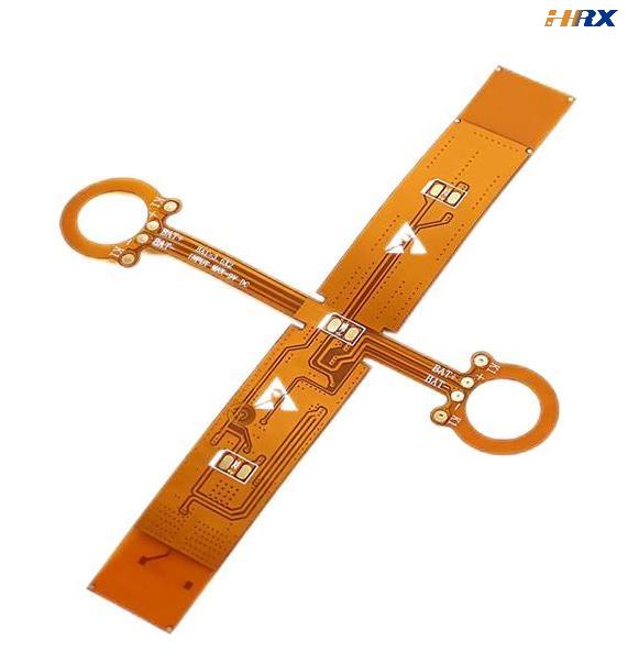
The essential skills and techniques of the best FPC (Flexible Printed Circuit) design engineers
- Apr 28,2025
-
Share
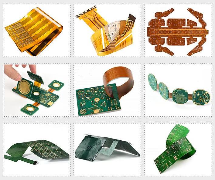
In the rapidly evolving landscape of modern electronics, Flexible Printed Circuits (FPCs) have emerged as indispensable components across a diverse range of devices, spanning from smartphones and wearable gadgets to advanced medical equipment and cutting-edge automotive systems. As a leading manufacturer specializing in the design and production of FPCs, PCBs, and Rigid-Flex Printed Boards, Shenzhen Huaruixin Electronics Co., Ltd. deeply understands the pivotal role that FPC engineers play in ensuring the seamless functionality, unwavering reliability, and peak performance of these flexible circuits. This blog post aims to comprehensively explore the key design techniques for FPC engineers, meticulously covering aspects such as circuit design, material selection, manufacturing processes, layout, and routing. By delving into these crucial areas, we strive to empower engineers to enhance their FPC design proficiency, steer clear of common design pitfalls, and stay ahead in the competitive realm of flexible circuit design.
Circuit Design: Laying the Foundation for Success
The circuit design phase serves as the bedrock of any FPC project, involving the intricate translation of an electronic device's functional requirements into a physical layout amenable to flexible circuit manufacturing. To ensure a successful circuit design, FPC engineers should adhere to the following essential tips:
Thoroughly Grasp Application Requirements: Before commencing the design process, it is imperative to gain a comprehensive understanding of the FPC's intended application. Key factors to consider include operating voltage, current, frequency, and environmental conditions. This in-depth knowledge enables engineers to select the most suitable components and design circuits that precisely meet the application's specific needs. For instance, in high-frequency applications, components with low parasitic capacitance and inductance are preferred to minimize signal degradation.
Simplify the Circuit Design: Strive to keep the circuit design as straightforward as possible while still fulfilling all functional requirements. A complex circuit not only increases the likelihood of design errors but also reduces the FPC's reliability and complicates the manufacturing process. Employ modular design techniques to break down the circuit into smaller, more manageable sub - circuits. This modular approach not only simplifies the design but also facilitates easier troubleshooting and maintenance.
Optimize for Signal Integrity: Signal integrity is of paramount importance in FPC design, particularly when dealing with high - speed signals. Minimize signal losses, reflections, and crosstalk by implementing proper trace routing techniques, impedance matching, and shielding measures. Differential signaling is highly recommended for high - speed signals, as it significantly enhances signal integrity and mitigates electromagnetic interference (EMI). For example, using differential pairs for data transmission in USB 3.0 FPCs ensures reliable data transfer at high speeds.
Prioritize Thermal Management: FPCs can generate substantial heat during operation, especially in high - power applications. Effective thermal management is crucial to prevent overheating, which can lead to component failure and reduced FPC lifespan. Utilize thermal vias, heat sinks, and thermal pads to efficiently dissipate heat. Additionally, carefully consider the thermal properties of the materials used in the FPC design to achieve optimal thermal performance. In automotive FPCs, where high temperatures are common, materials with excellent thermal conductivity are often chosen.
Material Selection: Choosing the Right Building Blocks
The selection of materials for FPC design has a profound impact on the flexible circuit's performance, reliability, and cost. When choosing materials, FPC engineers should take into account the following key factors:
Substrate Material: The substrate material forms the foundation of the FPC, providing mechanical support and electrical insulation. Popular substrate materials in FPC design include polyimide (PI), polyester (PET), and liquid crystal polymer (LCP). Each material offers distinct properties and advantages, such as flexibility, temperature resistance, and electrical performance. For applications requiring high - temperature resistance, polyimide is often the preferred choice, while PET is suitable for applications where cost - effectiveness and moderate flexibility are required.
Conductor Material: Copper is the most widely used conductor material in FPC design due to its outstanding electrical conductivity, thermal conductivity, and mechanical properties. The thickness and width of the copper traces must be carefully determined based on the circuit's current - carrying capacity and signal integrity requirements. Thicker copper traces are typically used for high - current applications to reduce resistance and prevent overheating.
Adhesive Material: Adhesive materials are employed to bond the various layers of the FPC together. Common adhesive materials include epoxy, acrylic, and silicone. The choice of adhesive depends on factors such as bonding strength, temperature resistance, and chemical resistance. Epoxy adhesives are known for their high bonding strength and excellent chemical resistance, making them suitable for demanding applications.
Coverlay Material: The coverlay material serves to protect the electrical traces on the FPC from mechanical damage, moisture, and environmental contaminants. Polyimide and polyester are commonly used coverlay materials. Select the coverlay material based on the required flexibility, temperature resistance, and electrical performance. In flexible display applications, a coverlay with high flexibility is essential to ensure smooth bending of the FPC.
Manufacturing Processes: Translating Design into Reality
The manufacturing process is a critical stage in ensuring the quality and reliability of FPCs. Key manufacturing processes involved in FPC production include:
Photolithography: Photolithography is the process of transferring the circuit design onto the FPC substrate using light and chemicals. This process begins with coating the substrate with a photosensitive material, followed by exposing it to light through a mask. The exposed areas are then developed to create the electrical traces. Advanced photolithography techniques, such as deep ultraviolet (DUV) lithography, enable the production of FPCs with finer trace widths and higher resolution.
Etching: Etching is used to remove the unwanted copper from the FPC substrate, leaving behind the desired circuit pattern. The FPC is immersed in an etching solution that selectively dissolves the copper. Precision etching techniques, such as dry etching, offer better control over the etching process and can achieve more accurate trace geometries.
Plating: Plating involves depositing a thin layer of metal onto the FPC substrate to enhance the electrical conductivity and corrosion resistance of the electrical traces. Common plating materials include gold, silver, and nickel. Gold plating is often used for contacts and connectors to improve electrical performance and prevent oxidation.
Assembly: Assembly is the process of integrating components onto the FPC to create a functional circuit. Various techniques, such as surface mount technology (SMT) and through - hole technology (THT), are used for component soldering. In recent years, advanced assembly techniques like flip - chip bonding have gained popularity for their ability to achieve high - density packaging and improved electrical performance.
Layout and Routing: Optimizing the Physical Design
The layout and routing of an FPC play a pivotal role in determining its functionality, reliability, and performance. Here are some essential tips for optimizing the layout and routing process:
Adhere to Design Rules: Strictly follow the design rules and guidelines provided by the FPC manufacturer to ensure the circuit's manufacturability and reliability. These rules typically cover aspects such as minimum trace width, minimum trace spacing, minimum hole size, and maximum aspect ratio. Deviating from these rules can lead to manufacturing issues and compromised circuit performance.
Maximize Flexibility: Given the flexible nature of FPCs, it is crucial to optimize the layout and routing to minimize stress and strain on the circuit. Avoid sharp corners, right angles, and tight bends in trace routing. Instead, use curved traces and fillets to reduce stress concentrations and enhance the FPC's flexibility. In applications where the FPC needs to be bent repeatedly, such as in foldable devices, proper routing design is essential to prevent trace breakage.
Consider Assembly and Testing Requirements: The layout should also take into account the assembly and testing
requirements of the electronic device. Provide adequate space for component placement, soldering, and testing operations. Incorporate fiducials and alignment marks to facilitate accurate component placement during assembly. Additionally, design test points to enable easy electrical testing of the FPC.
Implement Design for Manufacturability (DFM) Techniques: DFM techniques can significantly optimize the layout and routing of FPCs, reducing manufacturing costs, improving yield, and enhancing reliability. These techniques include minimizing the number of layers, using standard component sizes and shapes, and avoiding complex geometries. By adopting DFM principles, engineers can streamline the manufacturing process and ensure consistent quality.
Avoiding Common Design Errors: Lessons Learned
Design errors can be costly and time - consuming to rectify, making it essential to take proactive measures to avoid them during the FPC design process. Here are some common design errors and strategies to prevent them:
Incorrect Component Selection: Choosing inappropriate components for the FPC design can result in performance issues, reliability problems, and compatibility issues. Always select components that meet the specific requirements of the application, including voltage, current, frequency, and temperature ratings. Conduct thorough component research and verification to ensure their suitability.
Insufficient Clearance and Spacing: Inadequate clearance and spacing between electrical traces, components, and other elements of the FPC can lead to short circuits, electrical interference, and mechanical problems. Strictly adhere to the design rules regarding clearance and spacing to prevent these issues. Use design tools with built - in design rule checkers (DRCs) to identify and correct potential spacing violations.
Ineffective Thermal Management: Poor thermal management can cause overheating, component failure, and reduced FPC reliability. Implement proper thermal management techniques, such as using thermal vias, heat sinks, and thermal pads, to ensure efficient heat dissipation. Conduct thermal simulations during the design phase to predict and address potential thermal hotspots.
Lack of Design Verification: Failing to verify the design before manufacturing can lead to costly errors and project delays. Perform comprehensive design verification, including electrical simulation, thermal analysis, and mechanical analysis. Use simulation tools to validate the design's performance and identify potential issues early in the design cycle.
Conclusion
FPC design is a multifaceted and challenging discipline that demands a combination of technical expertise, creativity, and meticulous attention to detail. By implementing the design techniques and best practices outlined in this blog post, FPC engineers can elevate their design skills, avoid common design errors, and create high - quality, reliable, and high - performance flexible circuits. At Shenzhen Huaruixin Electronics Co., Ltd., we are dedicated to providing our customers with top - notch FPCs, PCBs, and Rigid - Flex Printed Boards. Our team of experts is always ready to offer technical support and guidance throughout the design process. If you have any questions or require further assistance with your FPC design, please feel free to contact us. We look forward to collaborating with you!
We cordially invite all industry professionals, whether seasoned colleagues or new partners, to join our discussion. Share your unique experiences, valuable insights, and encountered challenges in FPC design. Through collaborative learning, we can drive innovation and shape the future of flexible circuit technology. Let's embark on this exciting journey of continuous improvement and set new benchmarks in the FPC design industry!

Let’s talk! We’ll provide the perfect solution for you!
-
 Huaruixin Electronics mainly produces printed circuit boards as the core business, to provide customers with one-stop solutions for FPC/PCB production, components sourcing and Assembly.
 - WHAT WE DO — PCB Design Solutions — Flex PCB Production — Components Sourcing — FPC&PCB Assembly
- PRODUCTS — Single Sided Flexible Circuits — Double Sided Flexible Circuits — Multilayer Flexible Cirucits — Rigid-Flex Circuits — FPC Assembly — PCB Assembly
- CAPABILITY — FPC Capability — Rigid-Flex Capability — PCB Capability — Assembly Capability
- Copyright © 2024 Shenzhen Huaruixin Electronics Co., Ltd. All Rights Reserved.
- Design By BONTOP