
Search


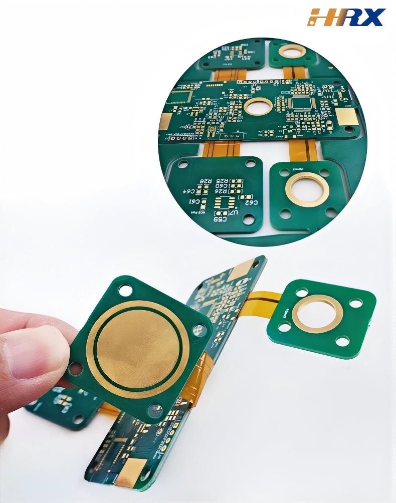
Rigid-Flex PCB Design in Electronics: How to Master Material Selection & Bend Radius (China Manufacturer Insights)
- Jun 11,2025
-
Share
When it comes to the design and manufacturing of Rigid-Flex Printed Boards (RFPCBs), several critical considerations must be addressed to ensure functionality, reliability, and manufacturability. Here’s a professional breakdown of key points tailored for the electronics industry:
Key Considerations for Rigid-Flex Printed Board Design & Manufacturing
1. Material Selection & Layer Stack-Up Engineering
Flexible Dielectrics: Use high-performance materials like polyimide (e.g., Kapton®), liquid crystal polymer (LCP), or PEN for flex layers to ensure thermal stability (up to 260°C), chemical resistance, and low dielectric loss. For high-frequency applications (5G, mmWave), LCP offers superior Dk/Df stability.
Conductive Layers: Opt for rolled annealed (RA) copper for flex regions requiring extreme flexibility or electro-deposited (ED) copper for smooth surfaces in high-speed signal traces. Thicknesses typically range from 9μm to 50μm, balanced against current-carrying capacity and bend resilience.
Adhesive Systems: Choose thermoset or thermoplastic adhesives (e.g., acrylic, epoxy) based on temperature tolerance and bond strength. Non-adhesive build-ups (e.g., polyimide films) minimize stack-up thickness for ultra-thin RFPCBs.
2. Bend Radius & Mechanical Design
Bend Radius Calculation: Maintain a minimum bend radius of 3–5x the flex layer thickness to prevent trace cracking. For example, a 0.1mm thick flex layer requires a 0.3–0.5mm bend radius. Simulation tools (e.g., ANSYS) should validate stress distribution during cyclic bending.
Bending Cycles & Fatigue Resistance: Specify cyclic durability based on application:
Consumer electronics: 10,000–100,000 cycles (foldable devices)
Automotive/industrial: 1,000,000+ cycles (robotics, under-hood systems)
Stiffener Integration: Place FR-4 or polyimide stiffeners at rigid-flex transitions to mitigate stress concentrations. Bonding techniques (e.g., epoxy lamination) must ensure uniform adhesion.
3. Trace Routing & Signal Integrity
Flex Region Routing: Use serpentine or meander patterns for traces in flex zones to allow elongation during bending. Avoid right-angle turns; implement 45° or rounded corners to reduce stress concentrations.
Impedance Control: Maintain tight tolerance (±10%) for microstrip/stripline traces in rigid sections. In flex layers, use controlled-depth vias and differential pairs for high-speed signals (e.g., HDMI, PCIe).
Thermal Management: Incorporate thermal vias in rigid regions to dissipate heat from power components. Flex layers may require thermal relief patterns to prevent delamination under thermal cycling.
4. Via Design & Fabrication Complexity
Via Types:
Through-vias: Penetrate entire stack-up, requiring precise alignment in multi-layer RFPCBs.
Blind/buried vias: Connect inner layers in rigid sections to minimize flex layer disruption.
Microvias: Laser-drilled (25–100μm) for high-density flex regions, but require careful plating to avoid cracking.
Via-in-Pad (VIP): Implement VIP structures with thermal reliefs in power planes to prevent pad lifting during reflow soldering.
5. Manufacturing Process Constraints
Lamination Press Control: Use vacuum lamination for flex layers to eliminate voids. Temperature profiles must balance adhesive cure and material degradation (e.g., polyimide softening above 300°C).
Plating Uniformity: Electroless/electro plating processes must ensure consistent copper thickness in flex regions, especially for fine-pitch traces (≤50μm).
Flex Layer Handling: Avoid mechanical stress during drilling and routing. Laser cutting is preferred for flex edges to reduce burrs and fraying.
6. Testing & Quality Assurance
Bend Cycle Testing: Subject prototypes to automated bending machines (e.g., dynamic flex testers) to validate fatigue life.
Electrical Testing: Perform in-circuit testing (ICT) and flying probe tests to check open/short circuits in flex regions.
Thermal Cycling: Subject boards to -40°C to +125°C cycles to evaluate delamination and trace integrity.
As a leading global manufacturer of FPC, PCB, and RFPCBs, Shenzhen Huaruixin Electronics Co., Ltd. specializes in addressing these complexities with advanced engineering and manufacturing capabilities. For project inquiries or technical consultations, visit www.hrxfpc.com or contact sales@hrxfpc.com to leverage our expertise in RFPCB design and production.

Let’s talk! We’ll provide the perfect solution for you!
-
 Huaruixin Electronics mainly produces printed circuit boards as the core business, to provide customers with one-stop solutions for FPC/PCB production, components sourcing and Assembly.
 - WHAT WE DO — PCB Design Solutions — Flex PCB Production — Components Sourcing — FPC&PCB Assembly
- PRODUCTS — Single Sided Flexible Circuits — Double Sided Flexible Circuits — Multilayer Flexible Cirucits — Rigid-Flex Circuits — FPC Assembly — PCB Assembly
- CAPABILITY — FPC Capability — Rigid-Flex Capability — PCB Capability — Assembly Capability
- Copyright © 2024 Shenzhen Huaruixin Electronics Co., Ltd. All Rights Reserved.
- Design By BONTOP