
Search


Rigid-Flex PCB: Critical Design, Manufacturing & Quality Control Details + Industry Application Examples
- Nov 18,2025
-
Share
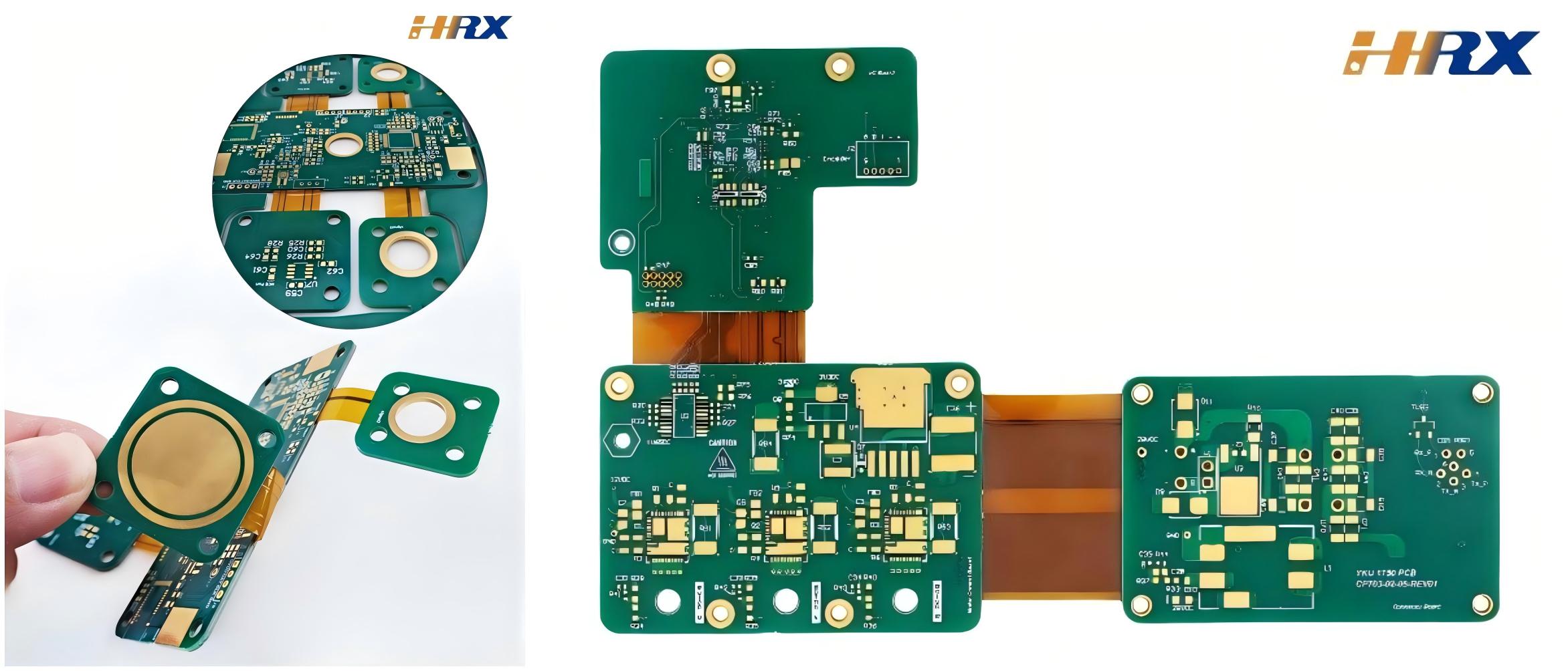
Rigid-Flex PCB (Rigid-Flex Printed Circuit Board) has emerged as a game-changing technology in electronic design, seamlessly integrating the structural stability of rigid PCBs with the dynamic flexibility of FPC (Flexible Printed Circuit). As a global ODM/OEM manufacturer specializing in FPC, PCB, and Rigid-Flex PCB solutions, Shenzhen Huaruixin Electronics Co., Ltd. brings decades of hands-on experience to share critical technical details, common pitfalls, and actionable solutions across design, production, and quality control—paired with real-world application examples that demonstrate the technology’s versatility.
Key Design Considerations for Rigid-Flex PCB (With Practical Examples)
Designing Rigid-Flex PCBs requires precision to balance flexibility and reliability. Below are critical details, common pitfalls, and tangible examples of how to avoid failures:
1. Bend Radius & Flex Zone Engineering
The minimum bend radius is a non-negotiable parameter—exceeding it leads to copper trace fracture, dielectric cracking, or premature fatigue. For standard polyimide (PI) flex layers:
Single-sided FPC: 1x the flex layer thickness (e.g., 25μm PI layer = 25μm bend radius)
Double-sided FPC: 2x the flex layer thickness (e.g., 25μm PI + 18μm copper = 86μm total thickness → 172μm bend radius)
Multilayer Rigid-Flex: 3x the flex stack thickness (e.g., 2x25μm PI + 2x18μm copper = 106μm stack → 318μm bend radius)
Pitfall Avoidance Example: A leading consumer electronics brand approached Huaruixin with a failed foldable smartphone hinge PCB. The root cause: a 90° bend radius of 150μm (below the required 200μm for its 100μm flex stack). Our engineering team revised the design to a 220μm bend radius, replaced straight traces with curved routing, and relocated 2 vias from the flex zone (adding 1.2mm clearance). The revised PCB passed 100,000+ fold tests—meeting the client’s durability requirements.
2. Layer Stackup Optimization for Target Applications
Rigid-Flex stackup must be tailored to the application’s environmental and mechanical demands. Key technical details:
Flex layers: Use 12.5μm–25μm PI (polyimide) for high flexibility; 50μm PI for rugged industrial use
Rigid sections: FR-4 (1.6mm–2.0mm) for standard applications; high-temperature FR-4 (Tg ≥170°C) for automotive/avionics
Symmetric stackup: Prevents warpage (e.g., Top: 25μm PI + 18μm Cu → Middle: FR-4 core → Bottom: 18μm Cu + 25μm PI)
Application Example: For a medical device client developing a portable ultrasound probe, we designed a 6-layer Rigid-Flex PCB with:
Flex zones: 2x25μm PI layers (total flex stack: 96μm) for 360° rotation
Rigid sections: 1.6mm FR-4 with 35μm copper for component mounting (transducers, connectors)
Symmetric stackup to avoid warpage during sterilization (autoclave cycles: 134°C, 20 minutes)The stackup design reduced the probe’s weight by 40% compared to traditional rigid PCBs and withstood 500+ sterilization cycles—critical for clinical use.
3. Trace Routing & Width/Spacing for Reliability
Flex zone traces: Curved (135°–180°) or diagonal routing to distribute bending stress; avoid 90° angles (stress concentration points)
Trace width: Minimum 0.1mm (100μm) for signal traces; 0.3mm (300μm) for power traces (reduces resistance during flexing)
Trace spacing: Minimum 0.1mm (IPC-2223 standard) to prevent short circuits under dynamic stress
Industrial Example: A robotics manufacturer needed a Rigid-Flex PCB for a robotic arm joint (10,000+ movement cycles/day). Their initial design used 90° trace angles and 0.08mm trace width—resulting in trace cracking after 2,000 cycles. Huaruixin redesigned the traces with 150° curves, increased width to 0.12mm, and added 0.15mm spacing. The revised PCB endured 50,000+ cycles without failure, improving the robotic arm’s mean time between failures (MTBF) by 250%.
Manufacturing Critical Details & Defect Prevention (With Case Studies)
Rigid-Flex PCB manufacturing demands tight process control to ensure consistency and reliability. Below are key technical details and real-world solutions:
1. Material Compatibility & Sourcing
Flex layers: High-purity PI (e.g., Dupont Kapton®) resistant to soldering temperatures (≥260°C for reflow soldering)
Adhesives: Epoxy-based adhesives (e.g., 3M™ 9460) for rigid-flex bonding (delamination resistance: ≥0.8N/mm per IPC-TM-650)
Coverlay: PI coverlay with acrylic adhesive (12.5μm–25μm) to protect flex traces from abrasion
Defect Prevention Example: A client experienced delamination in their automotive Rigid-Flex PCBs (engine compartment application: -40°C to +125°C). Root cause: Low-quality adhesive with poor thermal stability. Huaruixin switched to a high-temperature epoxy adhesive (Tg = 180°C) and sourced PI from Dupont. Post-redesign, the PCBs passed 1,000 thermal cycles (-40°C to +125°C, 1-hour dwell) without delamination—meeting automotive OEM standards (ISO 16750).
2. Lamination Process Control
Temperature: 185°C ±5°C (epoxy adhesive curing temperature)
Pressure: 250 psi ±20 psi (uniform pressure across rigid and flex sections)
Vacuum: -95 kPa (removes air bubbles that cause voids)
Time: 75 minutes ±5 minutes (sufficient curing for full adhesion)
Aerospace Example: An aerospace client required Rigid-Flex PCBs for a satellite’s communication module (vacuum and extreme temperature environment). Their previous manufacturer used atmospheric lamination—resulting in 15% voids (detected via X-ray). Huaruixin implemented vacuum lamination with precise temperature/pressure control, reducing voids to <1% (meets IPC-6012/2223 aerospace standards). The PCBs successfully passed NASA’s thermal vacuum testing (-150°C to +120°C).
3. Laser Drilling & Plating for Microvias
Microvias: Laser drilling (CO2 or UV laser) for vias ≤0.15mm (avoids mechanical stress on flex layers)
Plating: Electroless copper plating (2μm–3μm) + electrolytic copper plating (18μm–25μm) for via conductivity
Desmear: Plasma desmear process (removes resin residue from drilled holes to improve plating adhesion)
Consumer Electronics Example: A smartphone brand needed a 10-layer Rigid-Flex PCB with 0.1mm microvias for its camera module. Traditional mechanical drilling caused flex layer damage (30% of prototypes failed continuity tests). Huaruixin used UV laser drilling (precision: ±1μm) and plasma desmear, achieving 99.8% via continuity. The PCBs supported 4K camera functionality and met the client’s high-volume production requirements (1M+ units/month).
Quality Control (QC) Key Checkpoints & Standards Compliance
Rigid-Flex PCBs require rigorous QC to meet industry-specific standards. Critical checkpoints include:
1. Dimensional & Mechanical Inspection
Coordinate Measuring Machine (CMM): Verifies hole positions (tolerance: ±0.05mm), bend radius (±0.02mm), and rigid-flex interface alignment (±0.1mm)
Bend Cycle Testing: 10,000–100,000 cycles (depending on application) with 100% continuity monitoring
Peel Strength Test: Measures rigid-flex bond strength (≥0.8N/mm per IPC-TM-650)
2. Electrical Testing
Flying Probe Test: Validates continuity (resistance <1Ω), short circuits (insulation resistance ≥100MΩ at 500V DC), and impedance (±5% tolerance)
In-Circuit Test (ICT): For high-volume production (tests component soldering and connectivity)
3. Visual & Non-Destructive Testing
Automated Optical Inspection (AOI): Detects trace cracks, coverlay damage, and solder defects (magnification: 50x)
X-ray Inspection: Identifies voids, via plating issues, and internal delamination (resolution: 5μm)
QC Example: For a medical device client (FDA-regulated), Huaruixin implemented a 4-stage QC process:
Incoming material inspection (100% material certification verification)
In-process inspection (lamination, drilling, plating)
Final electrical testing (flying probe + ICT)
Destructive testing (1% sampling for peel strength and bend cycle validation)The PCBs achieved FDA 21 CFR Part 820 compliance, enabling the client’s device to enter clinical trials.
Key Industry Applications of Rigid-Flex PCB (With Technical Use Cases)
Rigid-Flex PCB’s unique properties make it indispensable across high-growth industries. Below are detailed application examples:
1. Consumer Electronics
Foldable Smartphones: Hinge PCBs with 200μm bend radius, 6-layer stackup (4 flex layers + 2 rigid layers), and curved trace routing (e.g., client: a top 3 global smartphone brand—10M+ units supplied)
Smartwatches: Miniaturized Rigid-Flex PCBs (15mm x 20mm) with 4-layer stackup, supporting heart rate sensors, GPS, and wireless charging (e.g., Fitbit-like wearable—reduced PCB footprint by 35% vs. rigid PCBs)
Laptop Cameras: Ultra-thin (0.8mm total thickness) Rigid-Flex PCBs with microvias (0.1mm) for 4K camera modules (e.g., Lenovo-like laptop brand—improved camera module reliability by 40%)
2. Medical Devices
Endoscopes: Flexible-tip Rigid-Flex PCBs (1.2mm diameter) with 2-layer PI flex layers, biocompatible materials (ISO 10993), and sterilization resistance (autoclave cycles: 500+)
Pacemakers: Implantable Rigid-Flex PCBs (5mm x 8mm) with hermetic sealing, low-power trace design (0.1mm width), and radiation resistance (100 kGy)
Portable Ultrasound Probes: 6-layer Rigid-Flex PCBs with 360° flex zones, high-density microvias (0.12mm), and thermal stability (-20°C to +60°C)
3. Aerospace & Defense
Satellite Communication Modules: 12-layer Rigid-Flex PCBs with high-temperature PI (Tg = 280°C), radiation-hardened components, and vacuum compatibility (10⁻⁶ Torr)
Drone Sensors: Lightweight (2g) Rigid-Flex PCBs with 4-layer stackup, shock resistance (50g), and vibration resistance (20Hz–2kHz)
Avionics Displays: 8-layer Rigid-Flex PCBs with high-speed signal routing (HDMI 2.1), impedance control (50Ω), and wide temperature range (-55°C to +125°C)
4. Automotive Electronics
ADAS (Advanced Driver Assistance Systems): Camera module PCBs with 6-layer stackup, waterproof design (IP67), and thermal cycling resistance (-40°C to +125°C)
EV Battery Management Systems (BMS): 10-layer Rigid-Flex PCBs with high-current traces (0.5mm width), voltage monitoring microvias (0.15mm), and flame-retardant materials (UL 94 V-0)
Infotainment Systems: Flexible interface PCBs with 4-layer stackup, touch sensor integration, and scratch-resistant coverlay (PI + hard coat)
5. Industrial Equipment
Robotic Arms: Joint PCBs with 8-layer stackup, 100,000+ bend cycle durability, and industrial-grade insulation (1kV)
IIoT Sensors: Wireless sensor PCBs (30mm x 15mm) with low-power design, flex antenna integration, and dust/water resistance (IP65)
CNC Machines: Control module PCBs with high-temperature resistance (150°C), rigid-flex connector integration, and shock resistance (30g)
Partner with Huaruixin for Your Rigid-Flex PCB Projects
Shenzhen Huaruixin Electronics Co., Ltd. is a trusted global ODM/OEM manufacturer with deep expertise in FPC, PCB, and Rigid-Flex PCB solutions. Our engineering team collaborates with clients from concept to mass production, leveraging advanced simulation tools, certified materials, and rigorous QC processes to deliver high-reliability, cost-effective products.
If you have a Rigid-Flex PCB project requirement—whether for consumer electronics, medical devices, aerospace, automotive, or industrial applications—our professional team is ready to provide tailored solutions. For more industry insights, technical resources, or to discuss your specific needs, visit our website: www.hrxfpc.com or contact us via email: sales@hrxfpc.com. Let’s collaborate, innovate, and bring your ideas to life!

Let’s talk! We’ll provide the perfect solution for you!
-
 Huaruixin Electronics mainly produces printed circuit boards as the core business, to provide customers with one-stop solutions for FPC/PCB production, components sourcing and Assembly.
 - WHAT WE DO — PCB Design Solutions — Flex PCB Production — Components Sourcing — FPC&PCB Assembly
- PRODUCTS — Single Sided Flexible Circuits — Double Sided Flexible Circuits — Multilayer Flexible Cirucits — Rigid-Flex Circuits — FPC Assembly — PCB Assembly
- CAPABILITY — FPC Capability — Rigid-Flex Capability — PCB Capability — Assembly Capability
- Copyright © 2024 Shenzhen Huaruixin Electronics Co., Ltd. All Rights Reserved.
- Design By BONTOP